Installation / Mounting Options for Hydro-Brake Optimum
Fitting and Mounting Options
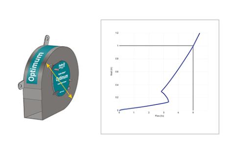
All our Hydro-Brake® Optimum flow controls are supplied as standard with identification engraved onto the rope handle so that they can be identified from cover level.
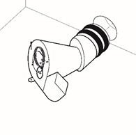
Fit to outlet pipe (XP)
Fit a Hydro-Brake® Optimum to a specified pipe diameter, whilst maximising the hydraulic efficiency that can be achieved for that pipe size. This makes it ideal for retrofit into existing chambers.
Mounting and fitting options
Our most popular fittings:
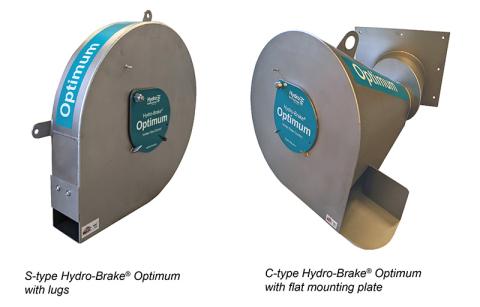
Hydro-Brake® Optimum S-type is supplied as standard with fitting lugs and C-type with a flat mounting plate.
For certain sites the standard fittings may not be possible. We have a range of different fittings / installation options to meet most site configurations.
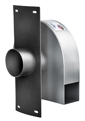
Push Fit
Mounted on a spigot to fit directly into the outlet pipe.
These units are mainly used for plastic chambers or square chambers where there is limited space, or for above-ground plastic GRP tanks.
They are also used in some cases where the unit is required to be removable for maintenance.
Curved Backplate
Add a curved backplate to any Hydro-Brake® order and save time not having to build a head wall in a chamber.
This option is available for any chamber size.
Other fitting options include:
Flange Fit
A PN Patteri flange fitting on the outlet of the unit, for direct fitting onto pipes.
A BS Pattern instead of a PN Pattern can be supplied if required.
Slide Mounted
Easy inspection / maintenance from cover level
Hydro-Brake® Optimum can also be supplied on a slide so that the unit can be pulled up from surface level.
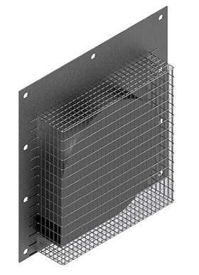
Mesh Guard Protection for Low Flow Units
Protection for very small units with inlets of <50 mm
There are now a variety of industry guidance documents applied at national and regional levels and they are not totally consistent in terms of their stance on minimum flow rates or minimum flow control sizes.
The approaches range from BS8582:2013, which states “controls smaller than 25 mm are possible if protected [from blockage]” up to the advice given by water companies, which can set a minimum acceptable opening size for adoptable flow controls for surface water only systems of >50 mm for protected orifices and >100 mm for unprotected orifices.
The mesh helps protect adoptable units with an orifice size between 50-100 mm.
To find out more download our white paper, Going with the Flow.
Options for Construction / Installation Assurance
Hydro-Brake® Optimum Chamber
Save time on site and reduce confined space entry. No coring or drilling, no headwall construction and reduced benching.
Specify a Hydro-Brake® Optimum ready installed into a purpose-built pre-cast, reinforced concrete chamber to ensure correct installation and improve CDM requirements.
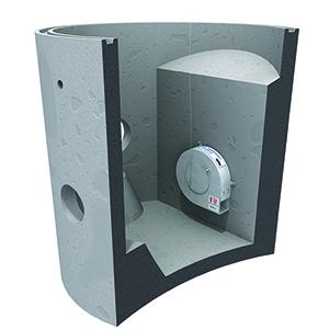
The Hydro-Brake® Optimum chamber is available in a range of sizes. The 1200 mm, 1500 mm and 1800 mm are the Marshalls CPM Perfect Manhole system which will fit exactly in place without the need for grouting for fast, safe and cost-effective installation.
The Marshalls CPM Perfect Manhole complies with BSEN 1917:2002 and BS5911-3.
Standard BS EN 1917:2002 chambers are used for 2100 mm and above.
The chamber is ready cored with holes to suit your site specification and comes with preformed options including benching, weir wall or headwall requirements.
The Hydro-Brake® Chamber option is also available for our Hydro-Brake® Orifice and Hydro-Brake® Agile flow controls.
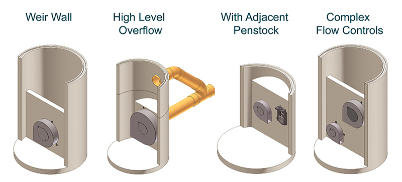
Additional Options for Hydro-Brake® Optimum Chamber
You can also select these additional features for your Hydro-Brake® Optimum Chamber
Weir walls - This chamber design includes reinforced concrete weir wall complete with a pre-mounted flow control. The weir wall can be constructed at various heights to suit design requirements.
High Level Overflows - This chamber includes an emergency overflow. The design incorporates a cored hole at the desired height to accommodate a reverse backdrop pipe arrangement.
Hydro-Brake® Optimum Chamber with Adjacent Penstock - this chamber incorporates a completely separate bypass via a penstock, although the flow control includes its own integral bypass to give additional drain down and full rodding and jetting access. The penstock is mounted on the headwall by the side of the Hydro-Brake® which can be opened for emergency discharge. This requirement is standard for a number of water companies.
For Hydro-Brake® Optimum units that are too small to fit a pivoting by-pass door the option of fitting a penstock alongside can provide a failsafe for draining down the system should a blockage occur.
For units small enough to benefit from a penstock, it is recommended that blockage protection should also be provided. Protection options include:
• Mesh guard over the inlet of the Hydro-Brake® Optimum
• Bypass weir in the flow control chamber
• Sacrificial orifice plate in front of the Hydro-Brake® Optimum
• Screens upstream of the Hydro-Brake® Optimum
• Level sensor system with Hydro-Logic® Flexi Logger data / telemetry device to alert if a blockage occurs.
To find out more about small units for low flows, download our white paper, Going with the Flow.